manufacturing of plastic water tank
1) Introduction of the product
1) Introduction of the product
Today in the world, when you look in the market plastic water tank are very competitive, highly selling and popular product. There are several reasons for it competitiveness.
- Shortage of water supply of government pipe lines.
- In rural areas pipe line water supply facility is not provided.
- Still people use natural water resource.
Because of above reasons to store water, plastic water tanks consumed highly.
For that higher consummation plastic water tanks should have special qualities.
The qualities are,
- Easy to install.
- No corrosions and highly hygiene.
- Low weight.
- Long life (able to with stand for UV rays).

Add caption


2) Chosen product details
Under the plastic water tank production in rotational moulding, the chosen product details are given below.
| Specification | Details |
| Water tank type | PE + Premium |
| Brand | ************** |
| Capacity | 500 liters |
| Total height | |
| Diameter | |
| Gross weight | 14 kg |
| No layers | double layer 1st layer – black 2nd layer – white |
| Used material | LLDPE-Food grade |
| 1st layer – thickness | |
| 2nd layer – thickness | |
| Inlet hole diameter | |
| Outlet hole diameter | |
| Over-flow hole diameter | |
| Top hole diameter | |
| Top hole closing type | Plastic cap with thread |
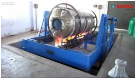
3) Manufacturing Process
The principle of rotational molding of plastics is simple. Basically the process consists of introducing a known amount of plastic in powder (granular) or form into a hollow, shell-like mold. The mold is rotated and/ or rocked about two principal axes at relatively low speeds as it is heated so that the plastic enclosed in the mold adheres to the mold and forms a monolithic layer against, the mold surface. The mold rotation continues during the cooling phase so that the plastic solidifies. When the plastic is sufficiently rigid, the cooling and mold rotation is stopped to allow the removal of the plastic product from the mold.


3.1 Introduction to rotational moulding
Rotational molding, known also as rotomoldingor, rotocasting, is a process for manufacturing hollow plastic products. For certain types of liquid vinyls, the term slush molding is also used. Although there is competition from blow molding, thermoforming, and injection molding for the manufacture of such products, rotational molding has particular advantages in terms of relatively low levels of residual stresses and inexpensive molds. Rotational molding also has few competitors for the production of large (> 2 m3) hollow objects in one piece.


The figure12.42 shows the moulding process called "Slush moulding process". The material filled to the mould, heated until liquid, pour out excess material, undergo for cooling and it forms uniform solid layer of plastic. In rotational moulding, and above "Slush moulding process" is developed.
Let's consider the developed method.

In the picture in your left hand as same as "Slush moulding process" material is filled to the cavity and heated up to liquid status, but in rotational moulding the cavity and mould rotates in certain speed and forms a uniform layer of plastic. This method leads to manufacture hollow plastic products very easily. Rotational molding is best known for the manufacture of tanks but it can also be used to make complex medical products, toys, leisure craft, and highly aesthetic point-of-sale products.
Reasons for using rotational moulding in manufacturing plastic water tanks.
- Complex parts can be moulded without need for post-assembly.
- Low machinery and material cost relative to production capacity.See the given graph below

- Double or more walled items can be produced.
- Ease of colour and material change.
- Minimum wastages.
- High production capacity on selected parts.

Lets discuss about manufacturing process of selected item in rotational moulding manufacturing process under capter 3.2 Manufacturing process in detail
The main attractions of rotational molding are:
- A hollow part can be made in one piece with no weld lines or joints
- The end product is essentially stress-free
- The molds are relatively inexpensive
- The lead time for the manufacture of a mold is relatively short
- Short production runs can be economically viable
- There is no material wastage in that the full charge of material is normally
- consumed in making the part
- It is possible to make multilayer products
- Different types of product can be molded together on the one machine
- Inserts are relatively easy to mold in
- High quality graphics can be molded in
The main disadvantages of rotational molding are:
- The manufacturing times are long
- The choice of molding materials is limited
- The material costs are relatively high due to the need for special additive
- packages and the fact that the material must be ground to a fine powder
- Some geometrical features (such as ribs) are difficult to mold
3.2 Manufacturing process in detail
- Plastic water tank manufacturing process mainly based on rotational moulding method. However it is not very complicated manufacturing method.In brief the procedure as following;
- The Polyethylene material granules are mixed with granules of black colour concentrators. These are extruded and strands are chopped as granules so as to achieve uniform distribution of carbon black.
- Then above powder is feed in to the mould in the required quantity.
- After that the burners of the rotational moulding machine are fired and heated around 300℃. Molten powders when rotated in the heat moulds form hollow storage tank. Then the second layer of the water tank manufacture by adding white colour Polyethylene material to the mould.
- After proper time when tank is ready, the mould is cooled in air removed the product.
- Then the each product is undergoing for required product quality tests. After tests the product is ready to the market.
- The basic steps of water tank manufacturing in rotational moulding divide into main four main steps as following;

(a) Material preparation and Mold charging
(b) Mold heating
(c) Mold cooling
(d) Part ejection or demoulding
Above four steps can be visualized as shown in figure below.


Note – In above manufacturing process, the process of manufacturing the steel mould which is needed in rotational moulding machine is discussed under topic "5.3 Production of the mould ".From here the production starts from (a) Material preparation and Mold charging.
3.2.1 Material preparation and Mold charging
Material preparation
The raw material (LLDPE) or granules which receive for the manufacturing process are not ready to use. The material undergoes to main steps.
- Grinding the material.
- Mixing with concentrators.
The grinding process is visualized below.


The material (granules) pours to the grinding head or mill to break into dust particles. After that through the cyclone, remove the larger particles and separate ideal particles for the manufacturing process.

In the grinding process, frictional heat increases the temperature of the metal cutting faces, the individual polyethylene particles, and the surrounding air. Because of that reason the temperature must be controlled so that it does not rise beyond the melting point of the polyethylene or to a critical softening temperature, prior to melting, when the particles begin to adhere to each other. This can cause blockages in the passage of new material entering the mill.


Grinding temperature has the most significant effect on the quality of the powder. The effect on dry flow and bulk density values are given with respect to the temperature vs Density variation during the grinding process.
Mixing with concentrators.
- High speed turbo blending
Dry blending is the best way of coloring rotational molding grade powders. It is attractive because cost savings can be made by purchasing bulk quantities of natural material and coloring this as required prior to molding. In this production black and white colour concentrators are used.
Other additives, such as UV modifiers, impact modifiers, thermal stabilizers, and antioxidants are mixed during the dry blending process.
After the above processes the material is ready to use for rotational moulding.

Before material process

After material process
Mould charging

After the material process, the material is feed in to the rotational moulding mould.
The amount of ** kg (details are not given by company) of the processed black colour LLDPE material feed in to the mould.


Then the mould is closed and ready to begin the heating process.
3.2.2 Heating
Let's discuss about the heating process.
Rotational molding begins with powder and then focuses on powder flow, sinter-melting or coalescence, densification, and cooling of the polymer. Heating is most important factor to obtain a good product.
General Anatomy of the Rotational Molding Cycle
Due to the new technology, it is possible to take continuous temperatures at various locations in and around the mold. Figure given below shows these temperatures for the entire heating and cooling cycle for a mold rotating in a near-isothermal hot air oven environment. As noted below, the outside mold surface temperature exhibits a classic first-order transient response to a step change in the environmental temperature. For most mold materials, there should be relatively little difference between the outside mold surface temperature and the inside mold surface temperature.
- The oven temperature nearly increased to 300℃. The below figure indicates the different temperature variations in the oven.


Heat controlling system panel board which is placed in the machine.

Characteristics of Powder Flow
During the rotational moulding we can see special characteristics of Powder Flow.
Rotational molding speeds are quite low, typically about 4 to 20 rev/min. As a result, the powder charge remains as a powder bed near the bottom of the mold throughout the early portion of the heating cycle.
This situation can be expressed in the figure given below.


Heat Transfer Concepts Applied to Rotational Molding

Three types of heat transfer occur in rotational molding. Conduction is the transmission of energy between solids. Energy is conducted through the rotational mold wall, through the stagnant polymer powder in contact with the mold wall, and through the polymer as it densifies, cools, and crystallizes against the mold wall. Convection is energy transmission through fluid flow. The heated air in the oven converts its energy through contact with the rotating mold surface, and the air inside the mold cavity is heated and cooled by convection with the inner mold surface, the rotating powder, and the densifying and cooling polymer mass. Radiation is electromagnetic energy interchange between hot and cold surfaces.Although radiation plays a minor role in heating and cooling molds and polymers.
Let's discuss about the mold heating .
Heating the Mold
Rotational molds are traditionally constructed of relatively thin, high thermal conductivity metals such as aluminum and steel. Typically, the mold absorbs substantially more energy than the plastic. As the mold is heating in a nearly constant temperature air environment, its rate of heating is essentially unaffected by the small amount of thermal heat sinks of due to plastic or the air in the mold cavity. As a result, the mold should exhibit a typical first-order response to a step change in environmental temperature. Mathematically, this is written as a conduction equation:
ρcp t dT/dθ= h(Tair– T)
Where ρ is the density of the mold material,cp is its specific heat, t is the mold wall thickness, T is its instant temperature, θ is time, Tair is the environmental temperature and is the convection heat transfer coefficient. If the initial mold temperature isT0, the instant mold temperature is given as:
(Tair–T)/(Tair–T0) = exp[–hθ/ρcpt] = exp[–hαθ/Kt]
Where =K/ρ cp, the thermal diffusivity of the mold material. Thermal characteristics for various mold materials. This model assumes that the temperature across the mold wall thickness is constant and that the heat transfer coefficient on both sides of the mold wall is the same. Technically, there is a thermal lag between the oven surface of the mold and the inner or mold cavity surface. The time at which the inside mold cavity temperature first begins to increase fromTmold,0 is given approximately by:
θ inside ≈0.0156L2/α
For all intents, the inside mold surface sees the outside mold surface energy in less than one second. Once the inner mold surface begins to heat, its temperature TL lags behind the outside mold surface temperature TWby approximately:
TL≈ TW– h(Tair– TW)L/2K
The temperature offset is about proportional to the convection heat transfer coefficient and the thickness and thermal properties of the mold material. High oven air flow, thicker molds, and molds of low thermal conductivity act to increase the temperature difference across the mold thickness. The rate of heating of both mold surfaces become equal when the heating time is approximately:
θ asymptote ≈0.45L2/α
The thermal offset across the mold thickness may be only a few degrees at best. The shape of the transient mold heating curve has been verified through measurements on stationary and rotating molds.1–3Table 4.2 lists values for convection heat transfer coefficients for various fluid media. Experimentally, the convection heat transfer coefficient for molds rotating in a hot air oven is on the order of 5 Btu/ft2 hr °F.
Time-dependent temperatures at various points in the molded part


Heating Powder & Track Temperature are the other heat transformations occur in rotational molding.
After the oven reach to 300℃, when first layer of LLDPE – black coloured layer formed the machine undergoes the process of forming process of second layer.


There is a special door to fill the secondary material into the mould. That is placed on the top of the machine. Before filling the secondary material several controlling steps have to be taken.

Filling white coloured secondary material in to the mould cavity
Total oven cycle time
First is the time needed to get the mold to the tack temperature. Since the polymer powder is in contact with only a portion of the mold during this time, this time should be nearly independent of the final part wall thickness. The second is the time needed to coalesce and densify the polymer against the mold surface. And the third is the time needed to ensure that the polymer is fully fluid and all bubbles have collapsed.
Tfinal. If the mold mass is mm and the mold has a heatcapacity of cpm, the amount of energy required is:
Qmold= mm cpm( Tfinal– T0)
The amount of energy needed to heat the powder charged to the mold from room temperature to its final fluid temperature,
polymer, final, is obtained from
polymer, final, is obtained from
Q polymer=mpolymer ∆hpolymer
From above equations we can calculate the Total oven cycle time
After that the machine undergoes to the process as same as processing the first layer.
Then the product is ready to perform the next step "Mould cooling"
3.2.3 Mould Cooling

In the oven when heating the temperature increased up to 300℃ . As the last main manufacturing process the mould should cool down to the room temperature.
When mould cooling there are two ways to cool down the mould.
- Quench cooling (water cooling)
- Slowly cooling (air cooling )
In this production process the method of air cooling(slowly cooling) is used to the mould to the room temperature.
Air Cooling


Highly powered blower fans are placed under the moulding machine to provide air which required for cooling.
In air cooling the speed and axial rotations of the mould keep as same as mould heating.
- Experimental cooling curves


3.2.4 Part ejection or demoulding


Technically, the ideal time for part removal from the oven is immediately after the polymer is fully dandified into a monolithic liquid film uniformly coating them old surface. At that time the product is removed from the mould.
This is the final process of manufacturing plastic water tanks.
- Note - Plastic cap with thread cut is needed component as the lid for the top hole of the water tank . That component is manufactured under plastic injection moulding separately from this process.
Required inlet and outlet holes are created by using plastic drilling method.
After the quality checking tests the product is ready to distribute to the market.
4) Materials used

In plastic tank manufacturing Polyethylene based materials are used such as LLDPE,HDPE,MDPE and etc.
For this production process Polyethylene based LLDPE polymer is use as the material for plastic water tanks.
4.1 Chemical details of material


The polyethylene product used to make all products is an extremely tough and durable lightweight thermoplastic material. The colour and ultra-violet stabilizers are compounded to give long-term resistance and stability to harsh sun. No chemical reactions take place during the manufacturing process and consequently there is no tainting of water with polyethylene. All of our tanks are manufactured using virgin linear low density polyethylene (LLDPE) which complies with AS/NZS2050, the standard for food grade material. The material is recyclable and can be repaired by a heat welding process if damaged.
Plastic, or polyethylene, water tanks are now the biggest selling sector of the water tank market and have been developed and tested in the market place over many years for the manufacture of water storage containers. It cannot rot or corrode, and is UV stabilized.
Water stored in polyethylene has no taste from the tank material because nothing leaches from polyethylene.
Physical properties of LLDPE
| Property | Value |
| Density | 0.92 g/cm³ |
| Surface hardness | SD48 |
| Tensile strength | 20 MPa |
| Flexural modulus | 0.35 GPa |
| Notched izod | 1.06+ kJ/m |
| Linear expansion | 20×10−5/°C |
| Elongation at break | 500% |
| Strain at yield | 20% |
| Max. operating temp. | 50 °C |
| Water absorption | 0.01% |
| Oxygen index | 17% |
| Flammability UL94 | HB |
| Volume resistivity | 1016 Ω·cm |
| Dielectric strength | 25 MV/m |
| Dissipation factor 1 kHz | 909090 |
| Dielectric constant 1 kHz | 2.3 |
| HDT @ 0.45 MPa | 45 °C |
| HDT @ 1.80 MPa | 37 °C |
| Material drying | NA |
| Melting Temp. Range | 120 to 160 °C |
| Mould Shrinkage | 3% |

Structure of LLDP
4.2 Applicableness to use the material

- Flexibility - In addition to UV and chemical resistance, LLDPE geomembranes exhibit a high degree of flexibility. Greater flexibility provides increased conformance to subsidence and differential settlement.
- Puncture Resistance - High puncture elongation properties make LLDPE liners ideal in applications where conformances to sub grade irregularities increase the possibility of puncture.
- Reflective Factor - Poly-Flex offers its LLDPE geomembranes in white as well as black. A white surface helps mitigate liner temperature extremes and aids visual inspection.
5) Tooling required
When considering the tooling most important thing is the type of rotational moulding machine, which is using for the production.
Several machine types are following,
- Open fired Rock Roll machine.
- Close Owen Rock Roll machine.
- Close Owen single arm single station Machine, 360° moveable mould.
- Close Owen three arm three stations Machine, 360° moveable mould.
- Shutled machine for mass production.

Biaxial rotational moulding plant 3 arm or Close Owen three arm three stations Machine, 360° moveable mould is the machine used in manufacturing process.
5.1 Basic tools required
Following Tools and machines which are used in manufacture process.
- Biaxial rotational moulding plant 3 arm – rotational moulding machine
- Chain pulley with stands. – to move heavy loads among the factory area
- Pulverizing Machine. – polymer milling machine
- High speed mixture. –mix the concentrators with grinded polymer
- Weighing machine. – to measure polymer weight
- Cutter machine for rejection tanks.
- Testing equipments
- Moulds.
5.2 Details of required tools.
The details are given only the most important machines for the manufacturing process.
- Biaxial rotational moulding plant 3 arm


Rotocaster..
|
|
|
|
|
|
|
|
|
|
|
Layout of the machine


2) Pulverizing Machine (single mill)
This machine is needed under "3.2.1 Material preparation" to grind the material.

| ||||||||||||||||||||||||||||||||||||||
- High speed mixture

This machine is needed under "3.2.1 Material preparation" to Mix grinded polymer with concentrators- Capacity 25 to 100 kg per batch. For granule
- Capacity 25 kg to 100 kg. Per batch for resin with pigment powder
- Moisture free blending and compounding with additives in different controlled temperatures.
- Stainless steel inner vessel and graded mild steel outer jacket provided with temperature sensors for monitoring the powder temperature and water jacket to avoid clotting of the resin during process.
- Process control timer switch to set and monitor the process.
- Provision for on line additives or pigment adding facility and breather valves on the lid.
- Pneumatic controlled powder discharge and lid opening arrangement.
- Digital display of powder temperature and water jacket temperature. With hooter /alarm for process timing indication..

Above mentioned machines are the most important machinery for manufacturing process.
5.3 Production of the mould
In this production process the metal mold is not manufactured by the water tank manufacturing company. The mould is manufactured by another company according to water tank manufactures' configurations.
Mostly these moulds are made from Aluminum ,Carbone steel or stainless steel sheet metal.
For this process the stainless steel moulds are used.
Process of manufacturing the mould

By using computer designed drawings sheet metal is cut and bended.
to obtain the cylindrical shape the metal sheet is fed

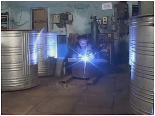
Argon welding and pilot torch welding is used to fix all parts of the mould.

Buffing process is needed to obtain perfect smooth finish of the mould

The mould is ready to use for manufacturing process.

6. Costing
Costing for the product can be calculated as following.
| Cost type | Costing criteria | Total(LKR) |
| Material cost | LLDPE+other material 1kg=150.00 | 150×14=2100.00 |
| Labour cost | 50%Material cost= Labour cost | 1400.00 |
| Overheads | 100% of material cost | 2100.00 |
| Net total | 5600.00 | |
| Profit | 40% | 2240.00 |
| Final cost | 7840.00 | |
Approximate retail selling price = 8500.00- 8900.00 LKR
7. Quality Considerations .
All the manufactured tanks undergo for product quality tests and obtained local and international level quality certificates.
This product has awarded following quality certificates
- ISO 9001
- SLS 147
- SLS 659
- SLS 935
8. Possible Defects may arise during the products manufacture.
With the new technology manufacturing defects are highly minimized .
But some defects can occur
- When heating the moulding the air bubbles will appear in the liquidized material and it will create patches and damage to the surface finish.
- In cooling cycle errors may occur and that will damage to the product strength.